

A borehole logging winch is part lifting machine, part depth-measurement system, and part data-acquisition platform. It must deploy sensitive downhole probes smoothly, carry the complete cable load, maintain controlled speed, and return an accurate depth signal. Selecting it from cable length alone leaves important mechanical and measurement risks unresolved.
The right specification begins with the heaviest and deepest planned job, then checks field access, power, transport, safety controls, and compatibility with the recorder. The result should support routine operation with margin rather than operate continuously at a limit.
For available deployment equipment, visit SAVIGEO and review its borehole logging winch and winch control system before matching cable capacity, load, speed, braking, and depth control to the survey.
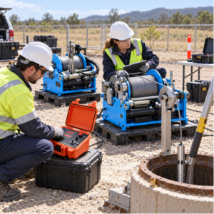
Calculate the complete suspended load
List the mass of the downhole probe string, cable head, centralizers, sinker bars, and cable suspended at maximum depth. Add fluid drag, friction in deviated holes, acceleration, and a credible allowance for minor sticking. Compare the case with cable breaking strength, recommended working load, termination rating, sheaves, frame, brake, and winch line pull.
Rated line pull may change with drum layer because effective drum radius increases as cable accumulates. Ask whether the stated value applies to a bare drum, full drum, or a defined layer. The weakest component governs the safe system.
SAVIGEO’s logging winch is intended for borehole instrument deployment. Final model selection should use the actual cable diameter, planned capacity, tool load, borehole depth, and operating environment.
Cable capacity is a geometric calculation
Drum capacity depends on core diameter, flange diameter, usable width, cable diameter, packing, and layer management. A nominal length stated for one cable cannot be assumed for another. Leave enough freeboard for orderly winding and avoid relying on perfect packing in field conditions.
The cable’s minimum bend radius must be compatible with the drum, measuring wheel, and sheaves. Repeated bending below the recommended radius damages armor and conductors. A level-wind mechanism should place the cable evenly without excessive fleet angle or crushing lower layers.
Speed, torque, and brake behavior
Logging needs smooth control at low speed as well as efficient travel between survey intervals. Maximum speed is less important than stable speed across changing drum diameter and suspended load. The drive should start and stop without shock loading or uncontrolled payout.
The brake must hold the maximum suspended load when power is lost. An emergency stop should bring the system to a controlled condition that does not create a more severe cable load. Mechanical, electrical, or hydraulic drive can all be suitable when power availability, maintenance skills, low-temperature behavior, and control requirements are considered.
A logging winch control system adds direction and speed commands with monitoring of values such as depth, tension, and current where configured. Confirm sensor interfaces and alarm behavior for the selected winch rather than assuming any controller is universally compatible.
Depth encoder and measuring wheel
The depth system commonly uses a measuring wheel pressed against the cable and an encoder that converts rotation to pulses. Accuracy depends on effective wheel circumference, cable contact, slip, wear, tension, routing, and encoder settings. Mud, ice, oil, or an incorrect clamping force can change the result.
Verify the depth channel over a known cable length before the job. Define zero at a physical measuring point and include the offset between the encoder reference, cable head, and sensor. During logging, maintain steady routing and record any event that changes cable tension or wheel contact.
Depth and downhole-probe signals meet in the PSJ digital logging recorder. Confirm encoder pulse settings, direction convention, sample interval, communication, and time synchronization before entering the borehole.
Tension monitoring and tool protection
Tension provides real-time information about system load. A gradual trend with depth may be normal; a sudden increase may indicate contact or sticking, while a sudden decrease can indicate support, slack cable, or a problem at the tool. Alarm thresholds should reflect the normal suspended load at depth and remain below component limits.
Tension data are also useful during interpretation. If several curves change at the same depth as a tension event, the response may be mechanical rather than geological. Save tension and speed channels with the primary logs when the system supports them.
Field layout and transport
Check vehicle access, ground bearing, anchoring, slope, wellhead clearance, rig-up height, weather protection, lighting, and cable handling space. The sheave must be secured and aligned so side loads are controlled. Barriers should keep personnel away from the tensioned line and rotating equipment.
For repeated deep work, an integrated borehole logging truck can provide a stable winch installation, cabin, equipment storage, and power distribution. Portable units suit remote or restricted access if the site can still support safe anchoring, cable routing, and operator protection.
Procurement checklist
- Maximum measured depth and required cable length, diameter, conductor count, armor, and bend radius.
- Complete tool-string mass plus cable weight, drag, deviation, dynamic load, and safety margin.
- Drum capacity and line pull stated by layer, with compatible level-wind and sheaves.
- Minimum stable logging speed, maximum travel speed, direction control, and soft start/stop.
- Holding brake, power-loss behavior, emergency stop, guards, anchoring, and overload protection.
- Depth resolution and accuracy, encoder interface, measuring-wheel calibration, and tool offset handling.
- Tension range, accuracy, alarms, display, and data recording.
- Power source, temperature, humidity, dust/water protection, transport dimensions, and service support.
ASTM D5753 and USGS borehole-logging guidance place equipment checks, depth control, operating records, and borehole conditions within the survey quality system . Local lifting, electrical, vehicle, and site-safety requirements also apply.
Frequently asked questions
How much cable should a logging winch carry beyond planned depth?
Allow for surface routing, sheave height, sensor offset, unusable termination length, operational contingency, and drum freeboard. The required margin is project-specific; it should be calculated rather than set as a single percentage for every job.
Is the highest winch speed the best choice?
No. Transit speed can save time, but logging speed is limited by sensor response, desired vertical resolution, data rate, and borehole risk. Smooth, repeatable low-speed control is often more valuable than a high maximum.
Why does depth differ between down and up passes?
Cable stretch, tension, measuring-wheel slip, backlash, tool drag, and different zero procedures can all contribute. Verify the encoder, keep routing consistent, compare repeat markers, and document any correction while retaining raw depth.
Conclusion
A logging winch should be selected as part of the complete wireline measurement chain. Calculate load and capacity, then verify speed control, braking, depth accuracy, tension, cable handling, and field layout. Share those inputs with SAVIGEO to define a winch and controller configuration for the planned borehole program.